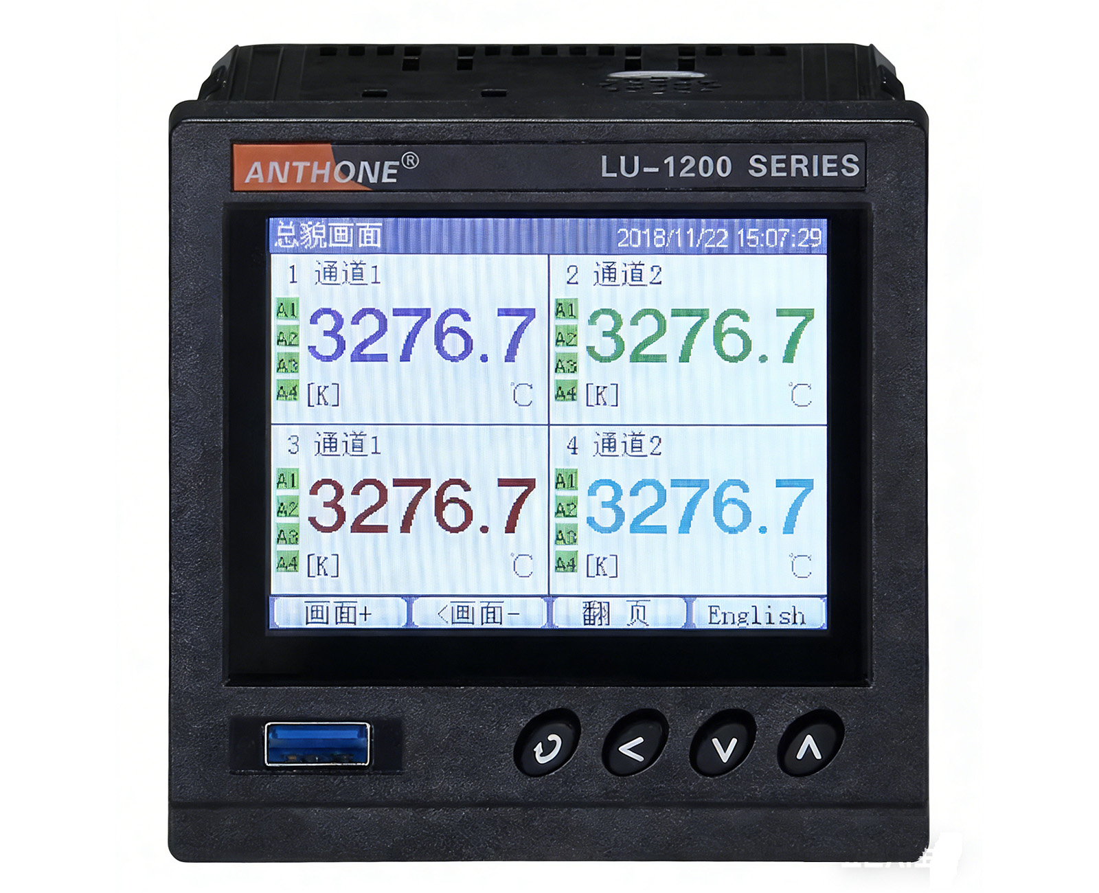
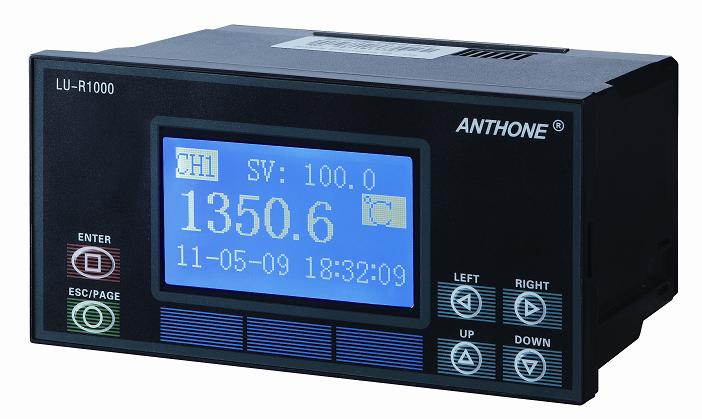
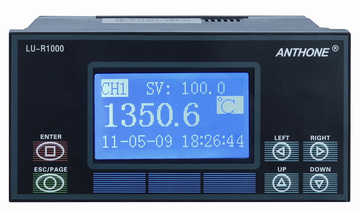
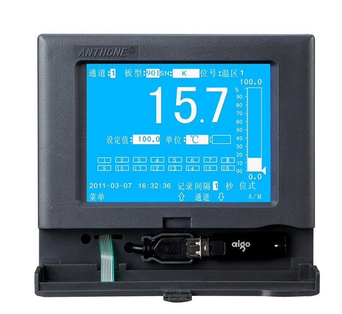
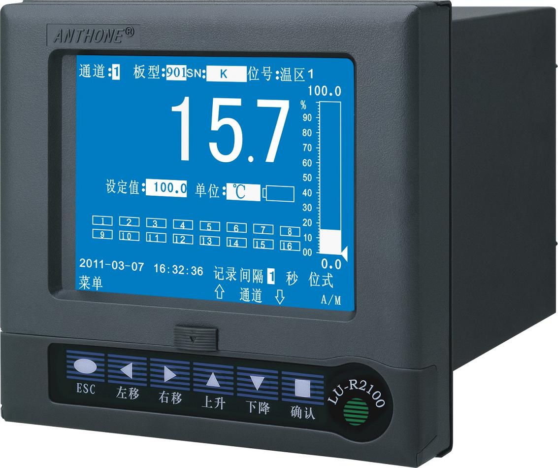
The LU-R/C1400 series intelligent paperless recorder combines recording and control in a single unit and provides fully switchable universal inputs: thermocouple, RTD, standard voltage and standard current signals; output control modes include PID control, on/off control, auto-tuning control and manual control.
The LU-R/C1400 can accept 1 to 2 PID control channels or 1 to 4 signal inputs; each control board has independent signal input, main output and alarm output, with full isolation between inputs and outputs.
Programmable PID control with program curves of up to 100 segments. Transmitter supply output is available.
Flexible data storage modes: the recorder has a total of 64M of internal storage space, and each channel has an independently adjustable recording interval (1-3600 seconds); users can select channels and recording intervals as required for data storage.
A high-capacity FLASH memory chip stores historical data with retention after power failure, and the internal storage time can reach 191 days to 1882 years. With USB interface technology, data can be transferred directly to a USB flash drive for longer recording time.
Connect to a portable computer or PDA via the RS232 communication interface to upload real-time/historical data directly, and use the host computer data management software or USB flash drive utility software to analyze, archive and print the data; the instrument can also connect via the RS485 communication interface to professional SCADA systems such as KingView and MCGS.
Powerful display functions: overview screen, extra-large screen, bar graph screen, real-time curve, historical curve, alarm screen, system configuration screen, channel configuration screen and print setting screen, etc. All curve screens support zooming, with an intelligent automatic playback function for historical trends featuring time and amplitude zoom, making alarm points extremely easy to find; a positioning query function allows direct queries of data for a specific year, month, day, hour, minute and second; the tag display function lets users name channels as desired.
The modular design makes configuration more flexible; different acquisition boards can be used at the same time, and the complete electrical isolation between inputs and outputs minimizes interference from power supply radiation on the acquisition boards and main board, greatly improving instrument reliability.
The user-friendly HMI provides operating hints on every screen, so users can operate and use the instrument easily without special training.
A Chinese/English bilingual display interface is also provided.
Operating parameter specifications
Sampling cycle: 0.5 s;
Basic error: ±0.2% F.S;
Real-time engineering value display accuracy: ±0.2% F.S;
Curve display accuracy: ±0.2% F.S;
Recall accuracy: ±0.2% F.S;
Bar graph: ±0.2% F.S;
Switching power supply: 85-264VAC, 12W, 50Hz±1Hz; or 24VDC.
Measurement input signal parameters
The LU-R/C1400A process control paperless recorder allows direct input of many signal types.
Input signal types include: 0~10mADC, 4~20mADC, 0~5VDC, 1~5VDC, thermocouples (B, E, J, K, S, T, Wre325, N), RTDs (Pt100, Cu50, Cu100), etc.
The signal types are as follows:
Type II: 0~10mADC, 0~5VDC;
Type III: 4~20mADC, 1~5VDC;
K-type thermocouple: 0°C~1200°C;
S-type thermocouple: 0°C~1700°C;
B-type thermocouple: 0°C~1800°C;
T-type thermocouple: -200°C~400°C;
E-type thermocouple: -200°C~1000°C;
J-type thermocouple: 0°C~800°C;
Wre325-type thermocouple: 0°C~2300°C;
N-type thermocouple: 0°C~1200°C;
Pt100:-200°C~600°C;
Cu50:-50°C~150°C;
Cu100:-50°C~150°C;
Flow signal types: 0-10mADC, 4-20mADC;
Pressure signal types: 0-10mADC, 4-20mADC.
Input impedance:
Current: 250Ω;
Voltage: 650KΩ;
RTD, three-wire resistance balance required;
Lead resistance < 10Ω.
Input channels: 1 to 4 channels, each channel may accept a different signal type.
Thermocouple cold junction compensation error: ±1°C.
Output signal parameters
Output modes:
0-10mADC current (RL<1000Ω, extendable to 2000Ω);
0-20mADC current (RL<500Ω, extendable to 1000Ω);
0-22mADC custom current (freely set by software);
Solid-state relay drive (12V/50mADC);
Relay contact output;
SCR zero-crossing trigger output (single-phase, three-phase);
24V power distribution: current < 200mADC.
Output interface modules:
I5: opto-isolated analog current output module (for 921 only the transmitter function is available);
U5: opto-isolated analog voltage output module, transmitter accuracy 0.2% F.S (for 921 only the transmitter function is available);
G1: solid-state relay drive voltage output module (DC15V/30mA) (not available for 921);
T5: opto-isolated single-channel SCR zero-crossing trigger module (triggers one bidirectional SCR rated up to 800A or two anti-parallel unidirectional SCRs) (not available for 921);
T6: opto-isolated two-channel SCR zero-crossing trigger module (triggers one bidirectional SCR rated up to 800A or two anti-parallel unidirectional SCRs) (not available for 921);
J5: relay contact output module (250VAC/3A normally open);
J6: relay contact output module (250VAC/0.8A normally open);
J7: dual relay contact output module (250VAC/0.8A normally open);
J8: relay contact output module (250VAC/3A normally open + normally closed);
J9: relay contact output module (250VAC/0.8A normally open + normally closed);
S2: opto-isolated RS232 communication module;
S4: opto-isolated RS485 communication module;
V6: isolated 12V/50mADC transmitter supply output module;
V7: isolated 24V/50mADC transmitter supply output module;
C8: opto-isolated single-phase SCR digital phase-shift trigger module (not available for 921).
Historical data storage
The storage space for recorded data is dynamically adjustable, and each channel has an independently adjustable recording interval; each channel can be enabled or disabled individually.
The fewer channels that are enabled and the longer the recording interval, the longer the historical data that can be recorded, and vice versa.
The internal FLASH storage space for recording channel history data is 64M; how long recorded data can be retained depends on the number of enabled channels and the recording intervals of the enabled channels, ranging from 191 days to 1882 years.